
- Hikvision Acusense (with AI Human & Vehicle detection / Strobe + Speaker)
- Hikvision ColorVu (Full Colour night vision surveillance)
- Hikvision Hybrid ColorVu (has both infrared and light capabilities)
- Hikvision PTZ Cameras (Pan, Tilt and Zoom / scroll around)
- Hikvision ANPR (number plate recognition solutions)
- Hikvision Darkfighter (for very low light areas)
- Hikvision Covert Hidden Cameras
- Hikvision Fisheye Cameras (panoramic or 360° cameras for wide coverage)
- Hikvision Thermal Cameras (overheating and skin temperature detection)
- Hikvision Solar Powered 4G Cameras
- Hikvision Turnstiles
- Hikvision TVI 4.0 Coax Cable Cameras & DVR Solutions
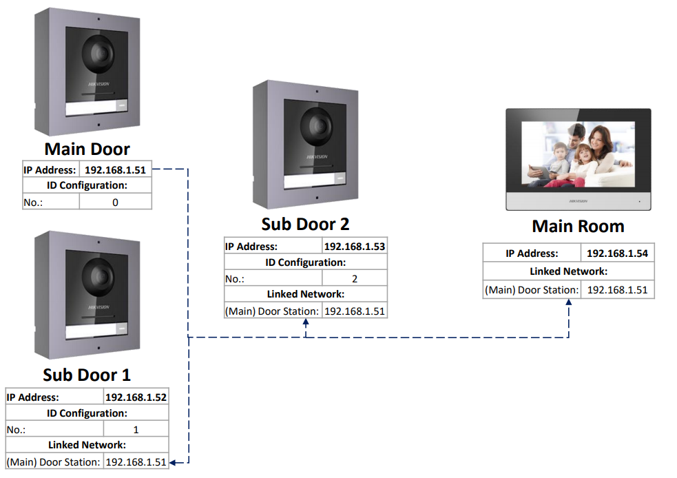
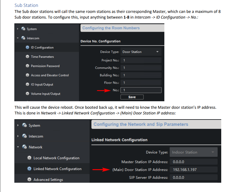
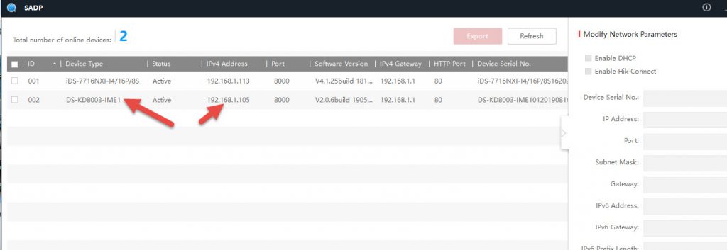
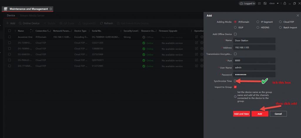
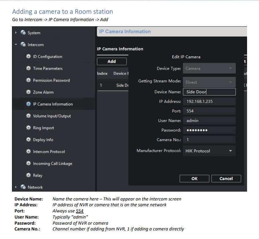
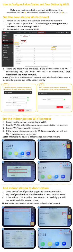
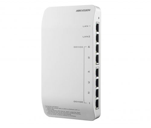
Hikvision Intercoms & Access Control


Comment on this FAQ
Logged in as cedcommerce. Edit your profile. Log out?
/* */