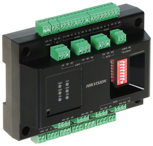


The DS-K2M002X from Hikvision is a versatile and intelligent access module built to extend and enhance the capabilities of access control systems. Supporting up to two doors, it connects to Hikvision access controllers via RS-485 and accommodates both RS-485 (OSDP) and Wiegand card readers, ensuring wide compatibility.
Designed for stability and security, the module supports fault detection for single-point reader failures and includes redundant processing to maintain system operation. With inputs for door contacts, exit buttons, alarms, and tamper switches, it provides comprehensive door state awareness and security event handling.
The unit also features six LED indicators for real-time feedback on power, communication, and door status, along with built-in support for battery charge/discharge functions. It installs easily via guide rail mounting and is suitable for professional-grade access systems across commercial, industrial, or institutional environments.
Key Features:
-
Controls up to 2 doors
-
Supports 4 RS-485 (OSDP) and 2 Wiegand card readers
-
Communicates with access controllers via RS-485
-
Alarm input/output and tamper detection support
-
LED indicators for power, comms, and door status
-
Built-in battery charging and discharging capability
-
Web browser configuration (via access controller)
-
Supports advanced access logic: interlocking, first-person-in, multi-factor auth (via controller)
Use Cases:
-
Commercial buildings: Reliable multi-door access with reader redundancy
-
Industrial sites: Secure entry points with alarm integration
-
Educational institutions: Multi-door interlocking and scalable control
-
Critical infrastructure: Tamper-proof access and failover reader support
This access module ensures robust and scalable access control when used with compatible Hikvision control panels, especially in environments where reliability and expandability are essential.